Page 1 of 2 12 LastLast
Results 1 to 10 of 12

Thread: Controlling start and end points of Custom linetypes

  1. #1
    Member
    Join Date
    2015-11
    Posts
    10
    Login to Give a bone
    0

    Default Controlling start and end points of Custom linetypes

    So in the attached image we have on the bottom a 6m line with shapes on it that are evenly spaced 1.2m (0.6m from the end shapes to the end of the line). Now I created a custom linetype out of this entire section. I would assume now if I was to draw a line exactly 6m long then it would appear exactly like the bottom shape, however it comes out like the line seen above, where the line from the end to the shape is short on one end and longer on the other (0.3m on the short end and 0.9 m on the long end). Why does it split it in this ratio and not an even 0.6 at either end?

    P.S. I defined the start and end points of the line at the start and end of the line seen in the bottom section.

    Thanks!

    Capture.PNG

  2. #2
    Certifiable AUGI Addict
    Join Date
    2001-03
    Location
    Tallahassee, FL USA
    Posts
    3,667
    Login to Give a bone
    0

    Default Re: Controlling start and end points of Custom linetypes

    We would need both the shape file and the linetype definition to help you.

  3. #3
    Administrator rkmcswain's Avatar
    Join Date
    2004-09
    Location
    Earth
    Posts
    9,805
    Login to Give a bone
    0

    Default Re: Controlling start and end points of Custom linetypes

    It depends on the linetype definition, but also the total length of the line vs. the spacing of the shapes.

    Using the "A" alignment code, AutoCAD will always add or subtract from the start and endpoints of a segment in order to maintain the defined spacing of the elements.
    You might try using the "S" alignment code instead, if you would rather the leftover spacing be distributed evenly between the elements.

    The two linetypes below have the exact same definition, except the top on uses the "A" alignment code, and the bottom one uses the "S" alignment code.
    Both lines start and end at the yellow lines.

    Attached Images Attached Images
    Last edited by rkmcswain; 2015-12-09 at 02:34 PM. Reason: clarification
    R.K. McSwain | CAD Panacea |

  4. #4
    Member
    Join Date
    2015-11
    Posts
    10
    Login to Give a bone
    0

    Default Re: Controlling start and end points of Custom linetypes

    Is that everything?
    Attached Files Attached Files

  5. #5
    Member
    Join Date
    2015-11
    Posts
    10
    Login to Give a bone
    0

    Default Re: Controlling start and end points of Custom linetypes

    Okay so I ended up just making the line type without the lines and instead just the shape. Looks like this now and I will just put it over a continuos line:Capture.PNG

  6. #6
    Member
    Join Date
    2015-11
    Posts
    10
    Login to Give a bone
    0

    Default Re: Controlling start and end points of Custom linetypes

    I really have no idea what you are trying to tell me rkmcswain and how to apply it...

  7. #7
    I could stop if I wanted to
    Join Date
    2015-10
    Location
    Colorado Springs, CO
    Posts
    369
    Login to Give a bone
    0

    Default Re: Controlling start and end points of Custom linetypes

    What he's saying is that the "A" code in the linetype definition will add or remove some line at the beginning and or end of the line segment so that all of the shapes are placed in specific places. The "S" code will allow for constant beginning and end sections, but allows for some variation in the placement (though still evenly spaced) of the shape along the line.

  8. #8
    Certifiable AUGI Addict
    Join Date
    2001-03
    Location
    Tallahassee, FL USA
    Posts
    3,667
    Login to Give a bone
    0

    Default Re: Controlling start and end points of Custom linetypes

    Quote Originally Posted by Hugh1994 View Post
    So in the attached image we have on the bottom a 6m line with shapes on it that are evenly spaced 1.2m (0.6m from the end shapes to the end of the line). Now I created a custom linetype out of this entire section. I would assume now if I was to draw a line exactly 6m long then it would appear exactly like the bottom shape, however it comes out like the line seen above, where the line from the end to the shape is short on one end and longer on the other (0.3m on the short end and 0.9 m on the long end). Why does it split it in this ratio and not an even 0.6 at either end?

    P.S. I defined the start and end points of the line at the start and end of the line seen in the bottom section.

    Thanks!

    Capture.PNG
    At 4.8 long it works since that's how long your linetype definition is. Not sure why you repeated the same shape and line four times, but reduce it to one and it should work with mutiples of 1.2 instead of 4.8. I placed the shape in my support path and changed the linetype definition to:
    Code:
    *GRPOST2,GRPOST2
    A,0,[GRPOST2,grpost2,s=10],12
    Seems to work as expected.

    Nice job on the shape!

  9. #9
    Administrator rkmcswain's Avatar
    Join Date
    2004-09
    Location
    Earth
    Posts
    9,805
    Login to Give a bone
    0

    Default Re: Controlling start and end points of Custom linetypes

    Quote Originally Posted by Hugh1994 View Post
    I really have no idea what you are trying to tell me rkmcswain and how to apply it...
    Quote Originally Posted by Coloradomrg View Post
    What he's saying is that the "A" code in the linetype definition will add or remove some line at the beginning and or end of the line segment so that all of the shapes are placed in specific places. The "S" code will allow for constant beginning and end sections, but allows for some variation in the placement (though still evenly spaced) of the shape along the line.
    What @Coloradomrg said.

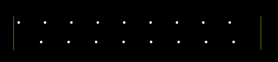
    For example, if you have a linetype definition that says draw a 1 unit dash and a 1 unit gap, and repeat, how do you want it to appear on a line that is 6.7 units long?
    The A alignment code ensures that each interior dash and gap are exactly 1 unit long. The starting and ending segments are the ones who are modified.
    The S alignment code distributes the extra space among the dashes and gaps (with the unfortunate side effect of ending with a gap in this case)

    codes2.png

    Here is the code for those two linetypes so you can see the difference

    Code:
    *A-Align-Code, __ __ __ __ __ __ __ __ __
    A,1.0,-1.0
    
    *S-Align-Code, __ __ __ __ __ __ __ __ __
    S,1.0,-1.0
    Last edited by rkmcswain; 2015-12-10 at 12:40 PM. Reason: added linetype def
    R.K. McSwain | CAD Panacea |

  10. #10
    Member
    Join Date
    2007-12
    Posts
    3
    Login to Give a bone
    0

    Default Re: Controlling start and end points of Custom linetypes

    Quote Originally Posted by rkmcswain View Post
    The S alignment code distributes the extra space among the dashes and gaps (with the unfortunate side effect of ending with a gap in this case)
    What a pity it does that - I was personally hoping it would lead to better complex linetypes with text in them - the "S" definition results in the dashes appearing over the text.

    I wish Autodesk had a linetype definition that resulted in the line being displayed as it is defined even if part of the definition is "chopped off" due to an odd length

Page 1 of 2 12 LastLast

Similar Threads

  1. custom linetypes
    By ndiamo4669 in forum AutoCAD General
    Replies: 4
    Last Post: 2010-06-28, 11:10 PM
  2. Replies: 8
    Last Post: 2007-03-27, 06:02 PM
  3. Replies: 21
    Last Post: 2007-03-12, 07:26 PM
  4. Controlling Insertion Points
    By BillyGrey in forum Revit Architecture - Families
    Replies: 5
    Last Post: 2004-11-14, 03:19 AM
  5. Controlling Insertion Points
    By BillyGrey in forum Revit Architecture - General
    Replies: 0
    Last Post: 2004-11-13, 12:53 AM

Tags for this Thread

Posting Permissions

  • You may not post new threads
  • You may not post replies
  • You may not post attachments
  • You may not edit your posts
  •